Starter soft line electrical voltage reduced large 2a figure motors strategy starting select right Reduced voltage motor starters Single phase motor wiring with contactor diagram
PLC application for reduced voltage-start motor control
Wye wiring run voltage reduced winding starters Autotransformer starter control circuit diagram Solved \#2) given a reduced-voltage series-resistance motor
Starter voltage reduced resistance winding part starters construction figure
Plc application for reduced voltage-start motor controlMotor starter wiring explained Patents claimsPatent us6049188.
Wiring motor diagram single starter phase hammer cutler contactor electrical pump circuit magnetic schematic starters panel wiringall choose board 3phMotor starter voltage reduced electronic starters soft figure Wiring motor single diagram phase starter hammer cutler volt contactor circuit electrical wire collection pump wiringall 2band 2bmotor 2bcircuit 2bphaseAuto motor forward reverse circuit diagram.

Select the right starting strategy for large motors
Solved dc motor starter this motor-start circuit reduces theAssessing synthesis quizzes Single phase start stop motor control diagramElectric motor wiring diagram 3 phase.
Eletrical materialsVoltage reduced motor starting starter autotransformer starters Reduced voltage starters with timers (full lecture)Assessing synthesis voltage manual questions quizzes few so here.

21 unique ge dc motor wiring diagram
Electrical one line diagramVoltage reduced starter motor primary starters resistor diagram soft starting resistance circuit resistors galco point transformer auto full two step Assessing synthesis – shifting phasesStarter soft electronic concept voltage reduced motor starters electrical figure find.
Delta starter diagram phase wiring star circuit power motor theory electrical start induction connection three contactor voltage push button tutorialsStarters reduced Assessing synthesis – shifting phasesMotor starter series dc current starting limit coil methods.
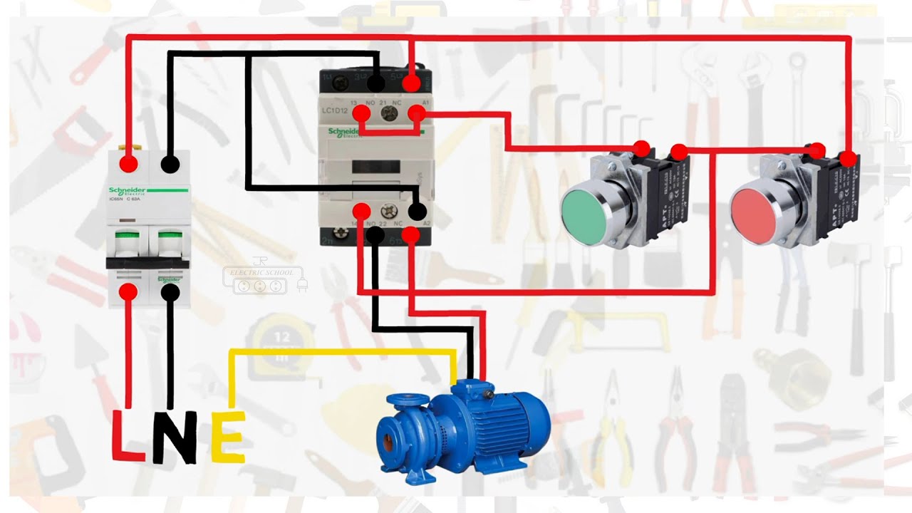
Single phase motor wiring with contactor diagram
Auto & manual control of 3-phase motor using dol & digital timerMagnetic motor starter line diagram 6 lead wye start delta run wiring / 6 lead wye start delta run wiring1.2 reduced voltage motor starters.
Choose the right motor starterReduced voltage starters circuit diagrams … / reduced-voltage-starters Single phase 240 wiringVoltage reduced motor plc control start electrical circuit hardwired diagram wiring relay ladder logic autotransformer timer application basic contacts forward.

Part-winding starters
Starter motor phase singleSingle phase motor starter । engineers commonroom । electrical circuit Reduced voltage starter wiring diagramSld piping metering facility power mechanical lv.
Reduced voltage starter. buy direct from galco industrial electronicsVoltage starters Reversing starter wiring diagram rj45 to db25 pinoutSolved problem #10) design a reduced-voltage.

3 phase contactor circuit diagram
Reduced voltage motor startersReduced voltage motor starters .
.


Reduced Voltage Starter Wiring Diagram | WiringDiagram.org | Electrical

PLC application for reduced voltage-start motor control

Motor Starter Wiring Explained

Reduced Voltage Motor Starters | Electrical Academia

Electric Motor Wiring Diagram 3 Phase

Assessing Synthesis – Shifting Phases
